
Design · 2024-11-26
Finned tri-clamp heat sink with PTFE thermal break
Can a standard 2 in tri-clamp double as the engine's cold-end heat sink if fins are machined into it?
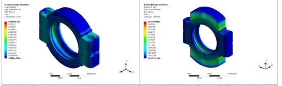
In simulation, yes. Under identical conditions the finned clamp reached a peak heat flux of ~0.032 W/mm² versus ~0.012 W/mm² for the plain clamp, roughly 2× or better heat rejection in still air. Not yet built or measured.
- Kind
- Design
- Status
- Simulated
- Date
- 2024-11-26
- Base part
- 2 in tri-clamp
- Material
- Aluminum
- Fins
- 31, ~1 mm
- Thermal break
- PTFE
- CAD / FEA
- SolidWorks / ANSYS Steady-State Thermal
- Boundary
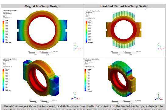
- Pipe 150 °C, air 25 °C, still
- Peak heat flux
- 0.032 vs 0.012 W/mm²
What it is
A 2 in aluminum tri-clamp redesigned with 31 radial fins so the clamp that holds the engine together also sheds heat from the cold side. A PTFE thermal break separates it from the hot section so heat isn't conducted straight across. Modeled in SolidWorks, simulated in ANSYS Workbench steady-state thermal.
Results
- →Peak heat flux 0.032 W/mm² finned vs 0.012 W/mm² plain (≈2.7× at the hottest point).
- →Report conclusion: finned clamp sheds heat about 2× faster than the original, with more gain expected in moving air.
- →Minimum surface temperature 147.9 °C finned vs 149.65 °C plain: aluminum conducts well enough that the fins run close to base temperature, which is what keeps fin efficiency high.
Lab notes
Why the clamp
Every joint on the engine is already a tri-clamp. Turning the clamp itself into the radiator adds cold-side surface area with no extra parts, no water jacket to leak, and no change to the modular stack.
Why a thermal break
A Stirling or thermoacoustic engine runs on the temperature difference between hot and cold ends. Any heat that conducts through the metal hardware instead of through the working gas is lost. PTFE (thermal conductivity ~0.25 W/m·K versus ~200 for aluminum) blocks that path while still sealing under clamp pressure.
Drawing
 Full drawing on EtsyDimensioned PDF, ready to send to a shop →
Temperature distribution
Heat flux
Caveats and next test
- Peak flux is a local value. The cleaner comparison is total heat rejected (W) at the same boundary temperatures, which ANSYS can report as reaction heat on the pipe face.
- Still-air convection is the worst case; any airflow over the fins widens the gap.
- Bench check: clamp both versions on the same heated pipe, log steady-state pipe and fin temperatures with thermocouples.
Notes from the design and simulation report posted to the channel community tab (Parts 1 and 2).
Related
Questions about this one? Ask in the Discord. It's the fastest way to reach me.